To complete this installation you will need to have a working knowledge and tools to remove the following:
- Inner door trim.
- Exterior mirror housing.
- Lower dash panel and lower A-pillar trims.
These are described in detail in the Bentley Manual or other DIY's available on internet.
Removing and installing the mirror housing will be required, as you have to feed two new wires through the hinge assembly of the mirror.
***Obtain any required radio codes before disconnecting battery***
Removing Mirror Assembly
First - Disconnect battery negative!
Remove inner door trim.
Fold the entire mirror housing forward to be able to remove it more easily.
Adjust the mirror glass fully in towards the vehicle on the inner edge.
Remove glass by pulling firmly on the outer edge, detaching the two heater element wires if fitted.
Locate 5 mm hole in the centre of the black plastic mirror base (may have a small plastic cap over it).
Push a screwdriver through this hole into the metal spring inside. The metal spring also has a hole drilled through it. The spring is only approximately 15 mm (approx half an inch) inside the housing.
Pull spring clip towards back of car (i.e. lever screwdriver handle towards front of car) - and unlock the spring clamp.
Lift painted housing directly up off of mirror base.
Unscrew black plastic lower mirror housing (two screws) and remove, taking care to unhook the black glass surround trim piece from the top of the casting.
Remove the mirror assembly by undoing the large torx bolt on the inner door skin.
Feeding new wires for Puddle Lights through hinge assembly
You now need to run two 000 979 009 repair wires into the vehicle through the mirror hinge from the outside (as per the existing wiring loom going through hinge assembly). You need to keep the terminals on the outside to plug into the new connector.
I bought 4 repair wires so that I could keep the maximum length of wire to feed through each hinge. I cut the terminal off one end of the repair wire very close to the end of the wire. This bare wire end gets fed through the mirror hinge from the outside to the inside of the mirror assembly. You have to feed the repair wire in from the outside as the terminals are too fat to feed through any part of the loom. This also avoids a splice halfway down the loom, which would not feed through as easily either.
Mark one wire at both ends so you know which is which. The LED needs to have the correct polarity feed.
Pin 1 on the Skoda LED plug is negative, Pin 2 is positive feed.
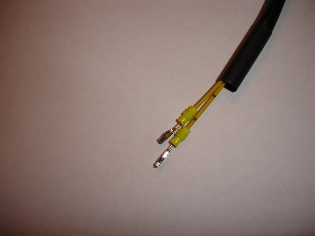
Place the yellow waterproof seal on the wires as shown in above photo (also note one wire has been marked). They have to be slid on from the cut off wire end before you feed the wires through the hinge. They will not go over the terminal without being damaged.
Do not put them into the new connector at this time. Leave them loose for the moment.
I put the two new wires inside a separate plastic conduit and was able to feed it through the hinge, rather than try and feed them through the original loom. This will take some patience to achieve.
Take the foam insulation off the inside of the mirror triangle. It is held on with the large white plastic clip only. This will allow you to work the loom up and down through the hinge slightly.
You can feed the new conduit down the hinge up to a certain point quite easily and get it started.. There is just a resistance point where the wires turn into the car at the bottom of the hinge. If you are very lucky it will poke straight through.
To feed the rest of the way - if you now pull the original loom up out of the hinge slightly (quarter of an inch to half and inch) and them push down on the new loom and pull the original one back in again, it will draw the new conduit with it. Then you hold the new loom down and pull the old one up again (so the new one stays put!), and then pull the old one down again, and it will keep feeding the new one through due to the friction against it.
You will start to see the new conduit poke through inside. You can then grab it with some pliers and pull it through. the rest of the way.
Celebrate your success!
Clip together two new Skoda LED mounting pieces, taking care to run the LED wires through the special plastic holders cast into the base (see photo). These holders are not on the standard base part. Note that the wires in the lower right of photo are NOT correctly positioned! Route the wires as shown by the yellow lines.

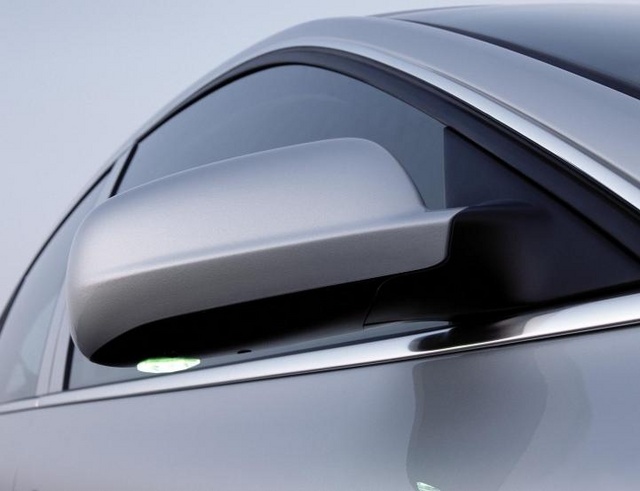
Refit new Skoda LED assembly to original mirror base making sure new electrical terminal is towards the front of the vehicle. It will sit inside outer painted housing near pivot point of mirror once everthing else is fitted.(see photo attached of an actual Skoda mirror)

Adjust length of new wiring to suit. The ends inside mirror should be just enough to allow the new 8E0 973 202 connector to join and hang down slightly, so that the connector sits up behind the hinge mechanism. Refer to your outer painted mirror housing to see how much clearance you will have for the plug and position as appropriate.
Place new 8E0 973 202 connector on wires, noting which wire you have plugged into terminal one and terminal two for correct polarity to LED.
Again, Pin 1 on the Skoda LED plug is negative, Pin 2 is positive feed.
Tidy wiring harness in mirror base and refit foam triangle. Refit mirrors now if you wish. Do not put painted cap on yet, although, again, make sure there will be clearance for the now joined LED connector (see above photo for guidance).
If you are proceeding OEM style, attach repair wires as below. You should at least have some sort of terminal here so you can unplug and take off the mirrors without disturbing the rest of the wiring.
Remove lower dash panel and lower A-pillar trims.
It is up to you how you extend the wires to the Comfort Control Module (CCM). You need to run two wires from each door to the CCM. The CCM is a black box mounted next to the steering under the dash, above the fuse box.
Important: Do NOT just earth the negative wire from the LED, as it is a switched earth. It must go into the CCM light circuit or the circuit will not work properly.
Note - these CCM connections are specific to the .:R32. Refer to additional notes below if you are fitting these lights to any other vehicle.
The positive feed goes to CCM terminal T23 / 20 (red / blue wire).
The negative wire goes to CCM terminal T23 / 21 (blue / grey wire).
This is the simplest place to connect the wires, but they can technically join anywhere in this circuit.
e.g. There is an 8 pin plug in the A-pillar that runs up to interior light roof harness. Pin 6 of this plug is the red/blue wire and Pin 1 is the blue/grey wire.
As my car has Interior Monitoring fitted as standard, both these wires are also available running to the B-Pillar switch that disables the Interior Monitor. I located them in the lower A-pillar harness adjacent to the door harness plug.
OEM style wiring.
Splice the 000 979 132 repair wire ends to the new loom from the mirror inside the door. These can be plugged into two empty terminals in the mirror plug, keeping note of which wire is your negative feed.
The female pins for the mirror terminal are the 000 979 131 terminals.
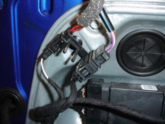
If you wish to have a separate plug in the door for the Puddle Light wires, please refer to parts list below. (The repair wires quoted for the Mirror plug are the same as the repair wires required for the additional plug). There should be a vacant position to secure it in the clamp on the inner door skin that secures the existing mirror plug:
Run two wires through door pillar bellows to 10 pin connector block in base of A-pillar. Select two vacant plugs and use appropriate 000 979 131 and 000 979 132 repair wires for each side of A-pillar connector. These small connectors will fit into any vacant terminal points in the middle of the 10 pin connectors.
Continue wires from A-pillar up to CCM
Splice matching "positive" wires from left and right door and join to wire from red / blue wire in the 23 pin plug on the CCM as noted above.
Splice matching negative wires from left and right door and join to wire from blue / grey wire of the 23 pin plug on the CCM as noted above.
Reconnect battery and test.
Disconnect battery again just to be safe whilst refitting door switches.
Replace mirror cap and door trims/switches etc
Reconnect battery for final time.
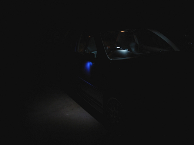
Marvel at the beauty of the puddle lights.
