Needle Sweep for Software version VWK501MH
These patches for enabling needle sweep were devised and created by "Bodie" and details are provided here with his very kind permission.
There are many many many hours of work involved in developing these patches. If you would like to make a small donation via paypal to the author to show your appreciation, please click here.
IMPORTANT NOTE
If you have ANY other software version besides VWK501MH and have ANY other ROM ID other than the ones listed below, these patches WILL NOT WORK
These needle sweep patches only work on Midline (half height MFA display) or Highline (full height FIS display) clusters.
Do NOT use on Lowline (no central display) clusters, they have different software!
Each patch is specifically customised to address the correct ROM ID
DO NOT TRY TO LOAD A PATCH INTO YOUR CLUSTER IF THE ROM ID DOES NOT MATCH - IT WILL NOT WORK!
There are many different ROM ID's currently identified for Midline (half height MFA display) and Highline (full height FIS display) clusters with software version VWK501MH
The only three valid patches developed and tested so far are the 00A4 , 10A4 and 92A3 ROM versions
The needle sweep patch overwrites any existing factory patch, but this new patch includes all the existing known factory updates
The patch also includes many safeguards to ensure it's correct operation
For example, if there is a low voltage condition or needles are not zeroed on the dials, then the sweep will not activate
This patch updates the Micronas MCU via a simple update to the EEPROM data
There are no other modifications required to the cluster to enable the needle sweep
Finding the ROM ID
The ROM ID can be identified as follows:
Method 1
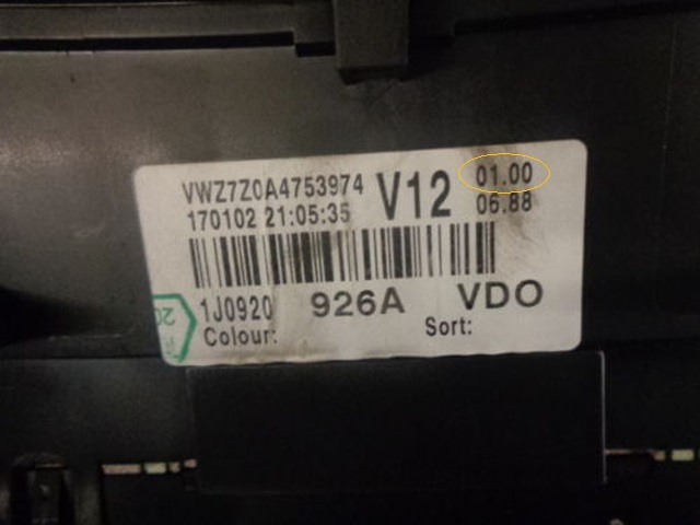
If you have the original part number sticker on your cluster, the ROM ID is encoded on the sticker:
Code 01.00 = ROM ID 00A4
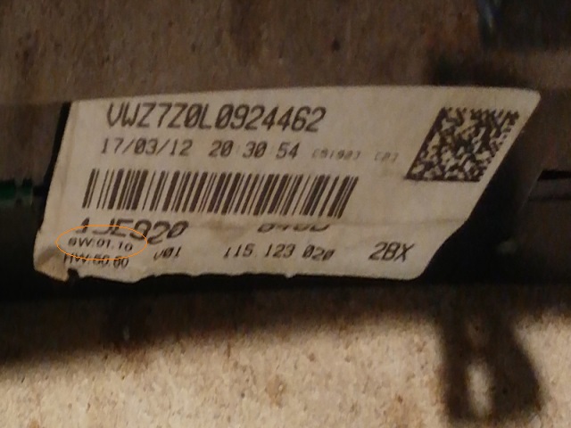
Code 01.10 = ROM ID 10A4
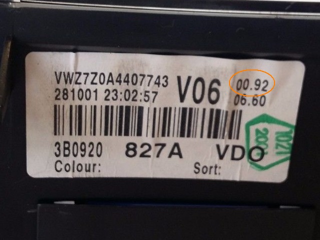
Code 00.92 = ROM ID 92A3
This is the sticker for ROM ID 00A4:
This is the sticker for ROM ID 10A4:
This is the sticker for ROM ID 92A3:
Method 2
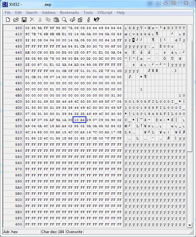
If you obtain an EEPROM dump and there is an existing factory patch in the cluster, there will be data commencing from the address 0x4F4 onwards
The ROM ID is located at address 0x4F8 and 0x4F9
For example, this screenshot shows a cluster with an existing factory patch with the ROM ID of 10A4:
If you do not have the original sticker, or you do not have any existing patch, then you cannot easily identify the correct ROM ID for your cluster.
IF YOU CANNOT ESTABLISH THE CORRECT ROM ID, PLEASE DO NOT PROCEED ANY FURTHER!
Installation
Back up existing EEPROM
Read EEPROM and write new data to the indicated addresses
Please ensure you use the correct patch data listed below for your ROM ID
Carefully check the new data - IT MUST BE EXACT
Data is checksummed and will not work if anything is incorrect.
If you are using the XVI32 hex reader program, there is an option under "Edit" tab to "Overwrite string" from a Hex String.
Highlight the byte address where you want to begin overwriting new patch data and paste the hex string patch data into the field box.
Press "OK" and it will overwrite the new patch data into EEPROM.
Confirm that patch data is correctly written into EEPROM file.
Load new EEPROM into cluster.
Log out, switch off ignition and remove key.
Sweep only activates after cluster performs an RPZD once, roughly 30 seconds after turning everything off.
If you watch closely, most needles will twitch as the RPZD drives them backwards against stops just before cluster enters "sleep mode".
Patch Data for ROM ID 00A4
Insert the following data, beginning at address 0x4F4 and ending at address 0x693
F0 1A 80 01 00 A4 00 00 00 00 00 00 00 00 00 00 00 0A A4 02 85 02 0A 0A 65 02 84 02 4C 24 85 00 00 00 00 00 00 00 00 00 00 00 00 00 00 00 00 00 00 00 00 00 00 00 00 00 00 00 00 00 00 00 00 00 00 00 00 00 00 00 F0 00 00 00 00 00 00 00 00 00 00 00 00 00 00 00 00 00 00 00 00 00 00 00 00 00 00 00 00 00 00 00 00 00 00 00 00 00 00 00 00 00 00 00 00 00 00 00 00 00 00 00 00 00 00 00 00 00 00 00 00 00 00 00 00 00 00 00 00 00 00 00 00 00 00 00 00 00 00 00 00 00 00 00 00 00 00 00 00 00 00 00 00 00 00 00 00 00 00 00 00 00 00 00 00 00 00 00 00 00 00 00 00 00 00 00 00 00 00 00 00 00 00 00 AD 36 08 29 07 C9 05 90 02 A9 04 0A 4C 18 A5 00 00 00 00 00 00 00 00 00 00 00 00 00 00 00 00 00 00 00 00 00 00 00 00 00 00 5A AC B8 0C A5 8A C9 0E F0 06 9C F8 0F 4C F3 0F AD F7 0F F0 09 E0 0E D0 F4 9C F7 0F 80 EF AD F8 0F D0 19 C0 03 B0 E6 E0 06 F0 0A E0 08 F0 0D E0 1E F0 09 80 5F A2 25 8E 2D 0B A2 1E A9 01 8D F8 0F C0 03 90 18 C0 0E B0 14 A9 CF 8D 6E 02 A9 F1 8D 70 02 A9 0F 8D 71 02 8D 6F 02 80 10 C0 1B B0 33 9C 6E 02 9C 6F 02 9C 70 02 9C 71 02 AD B0 16 8D 72 02 AD B1 16 9C 73 02 AD 20 17 8D 6C 02 AD 21 17 8D 6D 02 A9 02 14 81 A9 20 1C 2C 0B 7A 68 A9 5D 48 5A 7A 7C 5F 56 01 00 00 01 85 1C 4C 01 85 1E 0E 00 A5 12 4C 00 A5 14 0F 00 57 49 4C 00 57 4B 0F 00 7F
This is what it should look like in the EEPROM if it is input correctly:


