Daytime Running Lights using Pulse Width Modulated Reduced Intensity High Beam Lights

I decided to add Daytime Running Lights to my .:R32, which came standard with Xenon headlights, so that precluded running the normal US-style system with reduced intensity Low Beam Lights.

I also did not want to run the Xenon's as a full intensity Daytime Running Light either, although this method has been used on some newer VW's.

VW actually market a Daytime Running Light retrofit kit (Part Number 1J0 998 055 A), however, it runs the Low Beam Lights (at full intensity) in addition to running the Parking Lights as well.

I discovered that on certain Canadian market BMW's, there was a relay used that operated their High Beam Lights at reduced intensity using Pulse Width Modulation in order to meet local requirements.

I managed to obtain a wiring schematic for the BMW installation and have adapted this Canadian market Daytime Running Light Relay to work on my .:R32.

It is your responsibility to check this modification is legal in your jurisdiction.

Please note, with the basic modification, the flasher DOES NOT WORK if the igntion is OFF (as the BMW Relay requires power to function).

If you add an additional "79" Relay into the circuit, then you can fix this issue and everything will operate as per standard.

This modification has only been tested on Mark IV European/Australian Specification Golf. It has NOT been tested on any other vehicle.

Be aware that even Bora's have slightly different headlight wiring to the Golf, so you will need to carefully compare wiring diagrams for ANY other vehicles.

If you have factory fitted Fog Lights you will also need to check your own cars operation to see whether the Fog Lights switch OFF when you select High Beam.

Some markets require the Fog Lights to extinguish when you select High Beam. Other markets require or allow either Park, Low or High Beams to be ON with Fog Lights.

If your Fog Lights switch OFF when you select High Beam - see extra note below.

What is this modification?

You are modifying your High Beam Lights to operate as a reduced intensity Daytime Running Light ("DRL").

High Beams operate at approximately 40% of their full intensity, so approximately 22 Watts equivalent (rather than full intensity of 55 Watts).

Only the High Beam Lights operates in this manner. No other external or internal lights run during DRL mode.

This is what they look like in operation:

Please note, however, if you do not choose to modify the High Beam Warning Light wiring (fully detailed below), then when the High Beams are in DRL mode, the High Beam Warning Light will also show on the dash at a reduced intensity as well (as a warning light). You may choose to keep this as a DRL warning light to show the system is active.

This is due to the location of the OEM connection for the stock High Beam Warning Light (the -A95- point in the wiring schematic) being in the Right High Beam Light fused supply.

Fear not, for I have detailed the modification you need to do if you want the High Beam Warning Light to only come on during proper full intensity High Beam operation.

Also refer to additional note below about Fog Light Relay, if applicable to your car.

Function in BMW

Relay was used on Canadian market Z3 and 3-series BMW vehicles to comply with Daytime Running Light requirement.

DRL's work with the Light Switch OFF and also when the Parking Lights are ON (with Ignition ON).

So on the BMW, the DRL's only go OFF if Low Beam Lights are actually switched ON.

Essentially, if Pin 1 / 56 of the Relay has power, then the DRL function is OFF

High Beam and Flash-to-Pass function still work as per normal.

These are the BMW Relay pinout functions in a BMW:

1 / 56 = 0.5mm² yellow wire = joins output of Headlight Switch "56" to indicate that switch is in Low Beam "ON" position - disables PWM output.

2 / 87 = 2.5mm² red/white wire = "56a High Beam" output to High Beam circuit feeding High Beam fuses.

4 / 85 = 0.5mm² brown wire = 31 Earth.

5 / 15 = 0.5mm² green/red wire = "15" Ignition sense input (fused 5A).

6 / 30 = 2.5mm² red = "30" battery power (unfused).

7        = 0.5mm² red/white wire = Front Fog Light "disabling" signal - PWM High Beam also works if Front Fog Lights ON (Canada wiring)

This pin acts as the "earth" for the OEM BMW Fog Lamp relay coil until full High Beam selected via Flash-to-Pass or High Beam Switch (which disables foglights if ON) - when full High Beam is selected, the Fog Lamp relay coil field collapses and fog lights extinguish.

8 / 86 = 0.35mm² white wire = High Beam sensor - disables PWM output when Flash-to-Pass activated or High Beam selected.

Adaption of BMW Relay to VW Golf IV

CARE - THIS SECTION SPECIFICALLY RELATES ONLY TO THE GOLF IV (1J model)

Schematic for basic modification:

Wiring Schematic for Daytime Running lights and Fog Lights WITHOUT High Beam Flash-to-Pass Fix

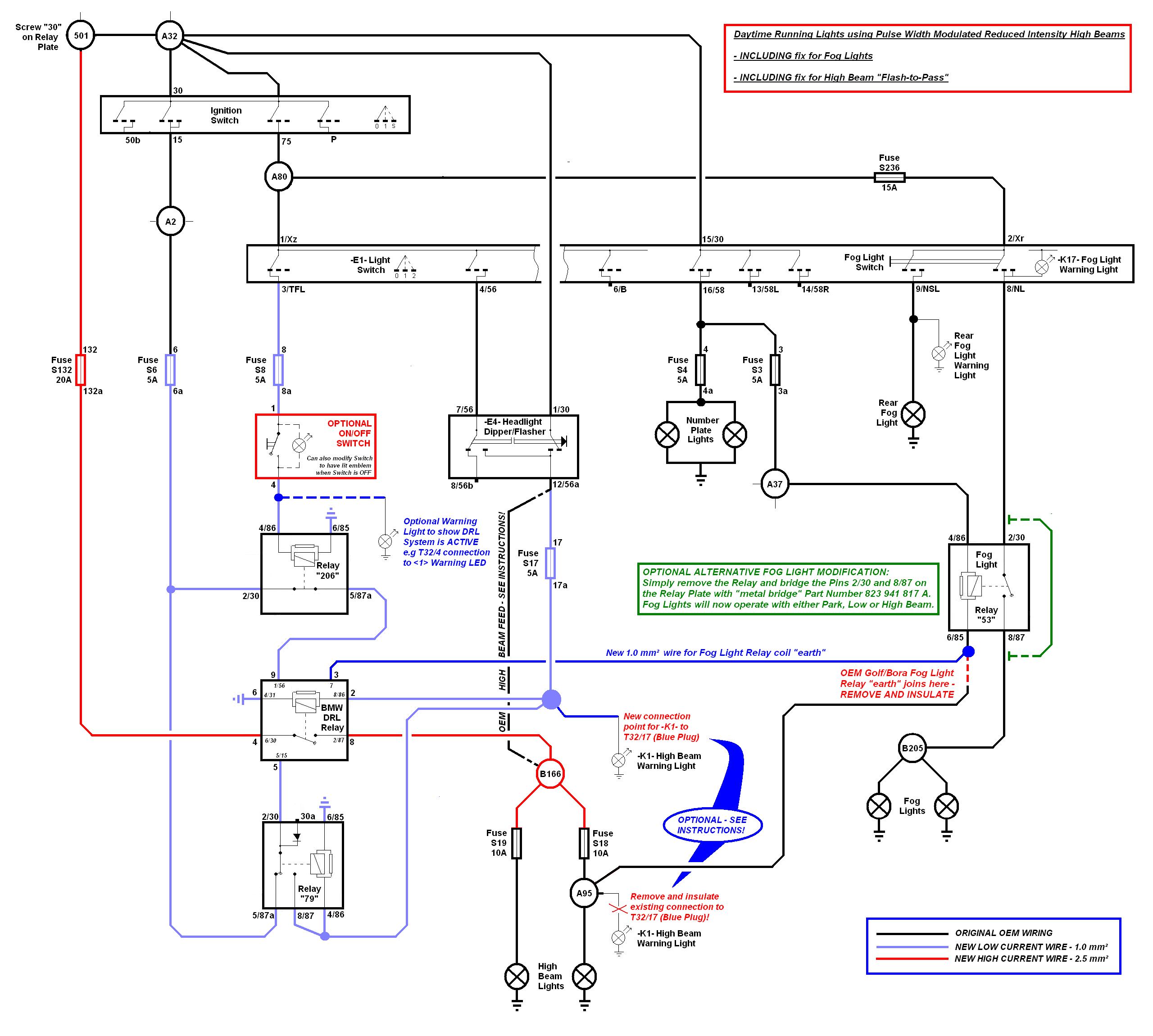
Schematic for modification with full OEM functionality of High Beam "Flash-to-Pass" Function with Ignition OFF:

Wiring Schematic for Daytime Running lights and Fog Lights WITH High Beam Flash-to-Pass Fix

If you want the DRL's to only work with the Headlight Switch in the OFF position (OEM VW Style), you have to add a "206" "normally closed" VW Relay into the circuit (as per diagram).

This is to enable you to use the TFL output on the VW Headlight Switch, so when the Light Switch is OFF, the DRL High Beams are ON.

As you can see, when TFL pin has power (Light Switch OFF), the "206" Relay coil is energised and cuts the feed to the BMW Relay Pin 1 / 56.

No power at BMW Relay Pin 1 / 56 means that DRL function is ON.

Pin 1 / 56 is powered by a 15+ feed, as this also makes the DRL's go off when you operate the starter (like other lights) to reduce the load on the battery.

If you just use a 75x (starter load reduction circuit) feed, then there will be no power to Pin 1 / 56 (via the "206" Relay), so the DRL's would come on when the starter operates.

When the Headlight Switch is turned to either Parking Light ON or Low Beam ON position, then "206" Relay is de-energised and power directly feeds to BMW Relay 1 / 56, turning OFF the DRL function.

Normal High Beam and Flash-to-Pass function still work as per normal when ignition is ON.

With this modification using only the BMW Relay and the "206" Relay, the Flash-to-Pass DOES NOT WORK if the igntion is OFF (as the BMW Relay requires power to function - fed through Pin 5 / 15).

If you just try to power Pin 5 / 15 with 30+ (Battery) power instead of 15+ (Ignition) to get around this problem, I believe the BMW Relay will be drawing current all the time and would eventually flatten the battery.

If you add an additional "79" Relay, then you can fix this issue (see Schematic - also linked above) and everything will operate as VW intended. The "79" Relay will allow the power feed to switch power to 30+ feed only whilst the High Beam stalk is actually operating, either Flash-to-Pass function (stalk pulled towards wheel) or High Beam ON (stalk pushed forward). The forward position still won't work with ignition OFF - same as on standard VW - however now the Flash-to-Pass function will work with ignition OFF.

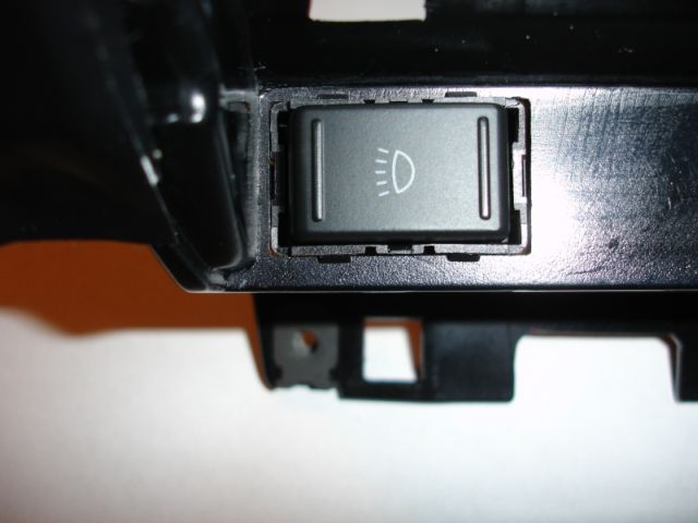
Note DRL ON / OFF switch in diagram. This switch is optional - you decide if you want one or not.

This switch will allow you to manually turn off the entire DRL system. This is handy if you are doing VAGCOM diagnostics etc, as otherwise the DRL's will be ON all the time with the ignition ON during diagnostic scans.

Any normal ON / OFF switch will work for this. See details below if you wish to use the OEM Škoda Roomster/Fabia ll DRL switch.

The BMW Relay Pinouts are also numbered differently compared to the standard VW Relays. Consequently, the numbered pins on the BMW Relay do not match the Pin designations on the VW Relay Socket. Please be aware of this difference when you are wiring up the Relay Socket to ensure the wiring matches the BMW Relay Pins correctly.

This is a cross-reference list for the Pin designations:

BMW Relay Pin = VW Relay Plate Socket

1 = 9

2 = 8

4 = 6

5 = 5

6 = 4

7 = 3

8 = 2

The pin works like this.

On VW relay plate each socket is numbered 1 - 9.

On BMW relay itself each pin is numbered 1 - 9 (only 7 actual pins of course).

On VW with VW relays the pin number matches the socket number when you plug in relay.

When you plug BMW relay in the pin numbers are actual reversed and do not match the designation properly

So Pin 1 goes into socket 9, Pin 2 into socket 8 etc etc.

Therefore you must wire the socket to match the pin function of the BMW relay without regard to pin number on the VW socket.

The schematic details the VW pin socket for wire. Inside the BMW relay on the illustration in small italic text is the BMW pin label printed on the BMW relay itself.

Škoda On/Off Switch

I found an OEM switch off a Škoda Roomster/Fabia ll with the proper DRL symbol on it. I cut a hole and mounted it next to the diagnostic plug, so it is hidden under the removable trim plate below the Climatronic.

This switch clips into a special molding on the Škoda, which is part of the entire dash assembly, so it was not secured very tightly in the VW application. I took the securing springs off an old Fuel Flap Release Button I had lying around and ground them down to about half their width. I popped the Škoda switch apart and slipped the cut down springs into the slots on the sides of the Škoda switch housing - now it sits tightly into the mounting hole I cut.

You can see the springs in this picture:

Depending on the position you mount the switch, there may also be some very slight clearancing of the dash panel frame that you can see above it in the second picture.

I have now had some aluminium frames made up to hide the mounting hole. If you would like one, please contact me via email link at top of this page.

Please note that this Škoda switch does not come standard with any provision to be illuminated by dash lighting.

There is also no standard provision to have any indicator that the Switch is either ON or OFF and therefore to also indicate whether the DRL system is active or not. This is why I also added the extra warning light to the circuit schematic.

After bench testing, the following was noted:

Pin 1 is for 12V INPUT.

Pin 4 has continuity if switch is rocked to left (i.e. switch will be ON if pressed on left side).

Pin 5 has continuity if switch is "flat" (i.e switch will be ON in flat position - more logical this way in usage).

No other pins appear to have continuity. Therefore it can also act as a TWO-WAY SWITCH - flipping 12V Pin 1 input between Pin 4 and Pin 5 output.

OEM Škoda Roomster setup uses Pin 1 input and Pin 4 output for ON position i.e switch is rocked to left to turn system ON

I soldered an LED and resistor into internal circuit using pins 1 - 5 as an experiment and nothing happened.

But with pin 1 - 4 active the LED lights up when switch is in OFF position - very strange...but very cool.

I have now soldered two amber LED's and suitable resistor into switch.

Now when the DRL system is switched OFF, for example when doing OBD scan, the switch emblem is lit amber as a visual reminder to turn the system on again.

If you do not wish to modify the switch internally then you can add an external LED warning to show the system is ON.

If you connect an additional feed off the output pin of the switch (either 4 or 5 as you have selected), then you can, for example, connect this wire to an external LED Warning Light.

A very convenient spare one is the Trailer Warning Lamp in European clusters, so you can simply connect this wire to the blue coloured T32 plug Pin 4 on the back of the cluster. (Please note that US clusters may not have an LED fitted inside the Cluster for this symbol).

This will then illuminate the green <1> symbol in the tachometer when the sytem is active and ignition is ON, like this (photo used with kind permission of Atty):

After modifying the Škoda Switch to have the "OFF" warning with the amber illumination, I decided that I preferred not to have any extra lights on in the cluster when driving, especially after also getting rid of the Cruise Control Light (see details in Cluster Programming).

I have now installed the updated 6R Polo Headlight Switch that includes the "DRL" Warning Light feature (full details on linked page).

Note that the green warning on the Polo Headlight Switch lights up whether anything is actually connected to the Pin 3 / "TFL" Pin or not, so the true status of the DRL sytem is still indicated by the Škoda Switch.

Parts List

61 35 8 368 039        BMW DRL Relay.

431 951 253 F           VW "206" Relay.

2 x 443 937 527         9-Pin Relay Socket (clips into Additional Relay Plate).

1 x 191 927 841        VW "79" Relay (optional - refer comments above in "Adaption of BMW Relay to VW Golf IV" section).

If you nominate to add this "79" Relay, you will also require one (1) additional 9-Pin Relay Socket 443 937 527.

1 x 823 941 817 A     Metal bridge (not required in all cases - see notes in section below regarding Fog Lights switching OFF when you select High Beam).

1 x 4A0 937 530        Fuse holder for Golf up to 2003 (clips to Additional Relay Plate).

Golf from model year 2004 on use 1 x 1K0 937 530 Fuse holder (clips to Additional Relay Plate) and 1 x 1K0 937 555 plastic dust cover.

1 x N 017 131 23       20 Amp Standard Fuse

3 x N 102 615 01       5 Amp Mini-blade Fuses

1 x ON / OFF switch of your choice (Škoda Roomster/Fabia ll switch I used is 5J0 941 503 WHS with 6-pin plug housing 8N0 971 636)

List of Repair wires required

"206" Relay

1 x 000 979 135 E

1 x 000 979 114 E

BMW Relay

1 x 000 979 133 E

1 x 000 979 135 E

1 x 000 979 227 E

1 x 000 979 114 E

1 x 000 979 212 E

Headight Switch

(1 x 000 979 133 E) - use spare end left over from Repair Wire used above for BMW Relay

Fuseholder on Additional Relay Plate

1 x 000 979 227 E

Fusebox

3 x 000 979 133 E - these Repair Wires fit the vacant Mini Fuse positions.

"79" Relay

(optional - refer comments above in "Adaption of BMW Relay to VW Golf IV" section).

2 x 000 979 135 E

1 x 000 979 114 E

Cluster

(optional - refer comments above in "Adaption of BMW Relay to VW Golf IV" section).

1 x 000 979 018 E - for Golf IV up to 2002

1 x 000 979 009 E - for Golf IV from 2003 on only

"53" Fog Light Relay

Not required in all cases - see notes below regarding Fog Lights switching OFF when you select High Beam.

1 x 000 979 114 E

Škoda Roomster/Fabia ll DRL Switch

1 x 000 979 114 E

Detailed Golf IV Wiring Modifications required

CARE - THIS DETAILED DESCRIPTION SPECIFICALLY RELATES ONLY TO THE GOLF IV (1J model)

You are modifying your electrical system. If you don't know the correct procedures to ensure continued safe operation of your vehicle, I would suggest you stop reading this now.

PLEASE DISCONNECT BATTERY BEFORE MODIFYING ANY WIRING.

Power for High Beam Lights comes directly through E4 Flasher Switch on Steering Column stalk, either through Pin 1 / 30 (for Flash-to-Pass function of High Beams) or through 7 / 56 which is the feed from the Headlight Switch.

Stock High Beams are then fed power through E4 Flasher Switch Pin 12 / 56a . This feed wire runs down to fusebox area where the wire splits into two and then feeds the unfused side of Fuses 18 and 19.

Unfortunately, the actual join point is buried inside the plastic ducting the harness goes through over the steering column, so it is essentially inaccessable without removing the entire dashboard.

I ran a completely new wire from Pin 12 / 56a on E4 Flasher Switch to unfused side of a new Mini-blade Fuse 17 (to be rated at 5 Amps only) which was a vacant position in my fusebox.

I unplugged existing wire at the E4 Flasher Switch Pin 12 / 56a and at the Fuses 18 & 19 and insulated the terminals (this keeps the stock wiring harness intact if you want to remove this modification at a later date).

The other way is to leave the column switch wire intact, find the two ends at Fuse 18 & 19 feeds, then rejoin them together and splice one wire to the new Fuse 17

See Diagram 1 and Diagram 2 for graphic of this procedure.

The fused side of Fuse 17 then goes to Pin 8 / 86 on BMW Relay.

AT THIS POINT, you may also wish to splice a new feed wire from here up to the Cluster High Beam Warning Light. This will fix the small issue of the High Beam Warning Light glowing dimly whilst the DRL's are on, as noted above in my initial description of this modification. Remove the existing wire (Pin 17 on the blue T32 plug on back of Cluster) and insulate.

Run a new wire from Pin 2 / 87 on BMW Relay and split into two and plug into Fuse 18 and 19 unfused side (previously removed as above). This wire needs to be high current as it is the new power feed to the High Beam Lights.

If you look at Fuse 6, you will see that VW have already kindly wired up the feed side of this fuse. This is a "15" feed (always ON with Ignition) This will be another new 5 Amp Mini-blade fuse.

Run a wire from the fused side of Fuse 6, then split to Pin 30 of new Relay "206" and also to Pin 5 / 15 of the BMW relay.

Fuse marked S132 will be a new 20 Amp fuse. I added this Fuse into a new Fuseholder attached to the Additional Relay Plate (see Parts List), as I had no spare fuse spaces in Fusebox (some cars may have another spare space).

This Fuse is fed from Screw terminal "30" located under the Relay Plate. Fused side runs to 6 / 30 of BMW Relay. This wire needs to be high current as it is the new power feed to the High Beams.

Run a wire from Pin 3 / TFL on Headlight Switch to unfused side of new Mini-blade Fuse 8 (5 Amps). Fused side of Fuse 8 will feed optional ON / OFF switch. (This goes to Pin 1 on the Škoda switch).

If you do not want to have the extra switch at all, just run wire from fused side of Fuse 8 to Pin 4 / 86 on "206" Relay.

If you do have the optional switch, then run output feed of switch to Pin 4 / 86 on "206" Relay.

I earthed all the Relays to the large Earthpoint visible on the Steering Column in front of the Additional Relay Plate.

All other wiring is straight forward - just join relay pins as per my diagram.

Additional wiring required if your Fog Lights switch OFF when High Beam is selected

If you do not do this modification to the wiring, then your Fog Light Relay (which is "53" Relay situated in Position 3 of Additional Relay Plate on RHD, Position 4 on LHD) will click on and off continuously when the DRL's are active.

Both schematics linked above include details of the modification you need to perform in relation to the operation of the Fog Lights. It also shows the disconnection of the existing High Beam Warning Light at the blue T32 Cluster plug Pin 17 as described in the previous section.

This is how the standard system works:

The coil on the standard Fog Light Relay 4 / 86 is supplied power from Fuse S3, so that Fog Lights can only work when Park Lights or Low Beam Lights are ON. When the High Beam is OFF then the Fog Light Relay coil 6 / 85 actually earths through the High Beam light filaments ( the current is so small you cannot even observe the light filaments glowing).

When High Beam is selected there is 12V on both sides of the relay coil, so the magnetic field collapses and the relay points open, stopping the Fog Light feed current via the relay points (between Pins 2 / 30 and 8 / 87 on the Fog Light Relay)

The relay is not a load reduction relay, it is simply there to switch OFF Fog Lights when High Beam Lights are ON.

When BMW DRL Relay is installed it will now continuously PWM the power to the High Beam circuit, which will cause the Fog Light Relay coil to rapidly energise/de-energise and rapidly open and close the relay points (causing the clicking noise you will hear).

Again, there are a couple of alternative remedies.

If you wish to have Fog Lights now operate with either Park, Low or High Beam, simply remove the "53" Fog Light Relay and bridge the Pins 2 / 30 and 8 / 87 on the Relay Plate with the metal bridge 823 941 817 A.

If you wish to keep your stock operation of High Beams OFF with Fog Lights ON then you will need to remove the existing wire going to Pin 6 / 85 on Fog Light Relay (which comes from the High Beam Warning Light join point -A95-) and insulate it.

Then run a new wire from Pin 7 of BMW Relay to Pin 6 / 85 on Fog Light Relay.

Return to Top

Return to Home Page