OEM+ Switches
There are a range of additional OEM+ switches available from VW/Audi that are utilised in various taxis, emergency vehicles and armoured Audis available in the German market. The picture above shows some of these switches mounted in the centre console of a Passat 3C taxi.
These include, amongst others, an "FS" Switch (originally used for Handsfree Device = Freisprecheinrichtung), an Interior Light Switch, a "TAXI" Switch, an "ALARM" Switch (available with either a black face or a red face) and a "Fan" Switch. Specific details of these particular switches are noted below.
The switches are identical in size & design to the Interior Monitoring Disable Switch, located on B-pillar trim on a Golf IV.
If you have a European specification car with the Fuel Flap Release Button near the handbrake, please note that these buttons are identical in size, however the texture and style of the press button part is slightly different (smooth, satin finish and flatter than the Fuel Flap Release Button).
The overall size of the switch body is 27mm x 27mm (1 & 1/16") with a depth of 40mm (1 & 9/16") behind the face. There would need to be some extra depth allowed for the plug wiring as well.
The switches have perfectly matching red illumination and will dim with the dashboard lights at night if you connect the appropriate pins from the switch to the vehicle dimmer circuit.
There is also a yellow "telltale" LED in the face of the switch which can be utilised to indicate that the accessory they control is ON. This has an independent circuit within the switch and is wired separately.
All these switches operate as a "momentary action" button only. If you require them to switch something on permanently, then you will require an additional "latching relay" or an appropriate circuit.
As you can see, they are a perfect size to fit on the vertical surface in the centre console in front of and above the sliding ashtray cover, or fitted in the console surrounding the handbrake, in a similar fashion to the Euro fuel flap release button.
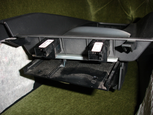
There is enough room to neatly mount three switches in this location. Some small clearancing of the bottom of the Radio Cage is also required for each switch. You will note that the square pegs on the rear face of the centre console mount through the square holes at the bottom of the Radio Cage piece:
Note: The extra switch in the above picture is my Daytime Running Light System ON/OFF Switch, which is normally hidden under the lower trim panel below the Climatronic. It is originally used in the Škoda Fabia II and Roomster for the same purpose.
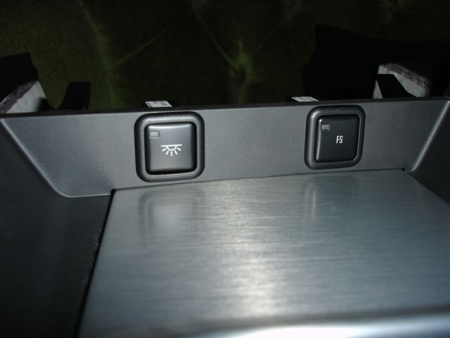
This is what the switches look like with centre console installed in .:R32:

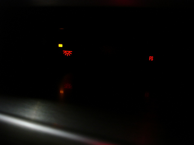
This is what the switches look like at night (note also Interior Light Switch is ON with yellow telltale lit):
 For those of you with the US style Centre Console with the large cupholders, these switches will mount perfectly in front of the front cupholder on the flat horizontal panel (photo used with kind permission of Kalini):

Please note there is also a switch mount number 1J0 862 292 2QL (black version) available from VW to replace the slotted coin holder at the rear of the console (highlighted in above picture).
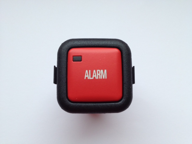
This is the "ALARM" Switch with red face:
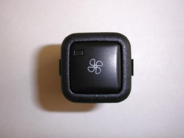
This is the "Fan" Switch: